


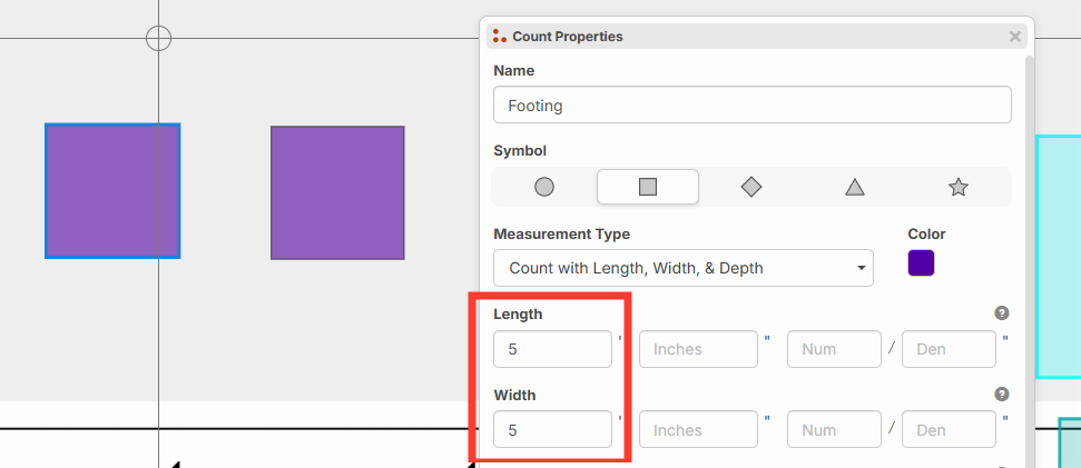
Collecting input: Length, Width, Height on Point Counts
Since we're using "Height" and "Depth" for our vertical Z-axis, we can't use "Height" for the 2D dimensions on a point count.
Our current naming system considers "Depth" as distance below ground (Z-axis), or below the plane drawn, and "Height" is distance above ground (also Z-Axis).
So that means we have "Length" and "Width" for 2D representation on a point count. In your opinion, which direction should be length, and which direction should be width?
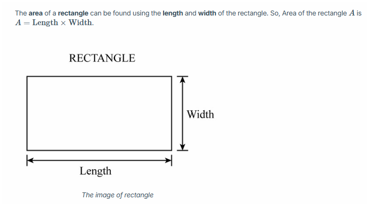
In many math diagrams, the length is horizontal, and width is vertical (and I realize having width be vertical is counter-intuitive). Often the length is supposed to be the longest dimension, but these are user entered fields, so we don't know which is longest at the time the user enters the distance.
Also, I checked and AutoCAD does a rect with "Length" as the X dimension and "Width" as the Y dimension. We may do the same.
Most people refer to it as "Length & Width" for the sequence of terms, so "Length" is almost always first. Generally X is first Y is second. Having "Width" be the Y dimension feels weird, but it's the only way I could think of to keep the sequence of X first Y second with this terminology (without using the word "Height", or reversing the terms to "Width & Length" instead of "Length & Width").
Just curious your thoughts.

IMO I like, X is length, Y is width, Z is depth/height
It really depends on how you are seeing it.
For example: A window or door can both use width when talking about it on top down plan. You can say, "what the width of the door" or "what is the length of the door", ether can be true. (And usually use thickness and height for other dimensions)
When looking on an elevation plan then, the height of the door is the Y axles as well. even though we call Z as height.
Length is generally used as the long something is, but like you said, it is a user input. And what really matters, is a standard or common view.
As long as you decide X is length and Y is width, everyone will just get used to it. Its just a plus that other programs/math match it.
Also, I like to think that on a plan page, the long end (Length) is usually the top/bottom and short end (Width) is the left/right sides. (So if you see the plan page a grid, X & Y makes more sense)
Also, you won't know what plans they are looking at.
Also Also, there is rise/run (Y/X)
You could even call each X, Y, Z (I think as long as it is common throughout, It should be fine) (But I do like saying Length / Width) (Maybe an option in setting)

I'm confused. Is this for changing the physical size of the objects that the system will generate on the screen when the user wants to do count takeoffs? Or is this for providing inputs for LxWxH on counts so that they can be then used for assemblies?
As long as I can enter 3 values for my counts to replicate LxWxH(or D), it doesn't really matter to me what you name it
@Jes these values would be used to calculate area and volume, as well as the display size of the count on the screen. If it's a circle it would prompt for diameter and depth (or height), and if it's a rectangle it would prompt for length, width, and depth (or height). We considered making a way to separate physical appearance of the point count from the area and volume calculation, but for now they are linked so that these dimensions impact appearance and measurement outputs.
Collecting further input:
We're thinking to add an "O" hotkey to rotate point counts (O for orientation) - for example a rectangle shape. Do you feel pressing "O" should:
- Rotate in 90 degree increments (and then maybe Shift + O for 45 degree increments)
- Rotate in 45 degree increments
Is "R" being used for anything?
"R" for Rotate. Also, it is on the left side of keyboard and easier to use with the left hand.
Since we use the mouse most the time with our right hand, our left hand is usually faster if it is set on home row.
Also, how about a Shift + R + Hold mouse button to custom rotate the item. (Think of it like the game asteroids, where the face of the ship follows the curser)
Hey while we're on the topic of hotkeys, I would love "H" to toggle the hide command when I click on a takeoff object to save time from needing to right click and physically select Hide
Hmmm...we have "R" already used for "Align selected nodes right". I guess we will have to use "O" or re-assign the align hotkeys to something like ALT + R or similar to open up "R" as an option.
I am of the opinion that material/assemblies should all show as Depth x Width x Length, where depth is the least variable dimension, width is somewhat variable, and length is the most variable.
Further, we should disambiguate dimension from orientation altogether. Simply let the user choose the mapping. For example:
x:depth
y:width
z:length
@Heber
I wouldn't like an alt mixed with a non-alt if they don't any relation, might confused people.
What are the other aligns assigned to? L, T, B?
Wouldn't having the aligns be near each other be better, like (J, K, L, I) or an Alt + ← or →, then rotate would make since with "O"
I would suggest having the A,S,D,W for it, but I do like the "A" being Arc
I’m a little confused about why we are doing this in this manner. Why don’t we just use an area once and copy and paste the rest, using the sections count as the count? Or if need be, allow the user to specify the dimensions directly (override takeoff dimensions), save in a template, and stamp away? This way rotations could be handled by grabbing a point on the area, holding a mod key, and dragging to whatever angle you like.
It just seems like counting 3D objects as 1D objects while wanting to treat them as 2D objects is a contortion of what the basic takeoff tools are supposed to be.
And can we just get on with custom key bindings?
@John, I totally agree with your point. We actually had an internal discussion about this yesterday. Ultimately, we will handle it both ways. In the future, we are planning to add the ability to create a "takeoff stamp" (which could be made up of either 1 takeoff section, or even a combination of area, linear, count - such as for hotel rooms), and this should accomplish what you are describing.
Also, yes custom key binding will be coming. We're just juggling a lot, but we'll get it in here as soon as possible.
@John, Its more of a speed thing. Setting up a count, then click click click, is faster than, setting up a SF, then copy paste, paste (Confirm), paste (Confirm), paste (Confirm)
The dimensions are just to get it closer to the size of the item.
On my end, I ran into an instance where putting L & W values where they're intended to go made the object misalign with the shape on the plan drawing, but had no effect on my formulas and calculations. Once rotation functionality is put in the issue with these counts not fitting neatly into their boxes will be resolved
@Jes We have rotation for point counts working locally. Just need to test it and a patch should go out reasonably soon.